contact us
Zhuhai Superconn Technology Co., Ltd.
Email: sales@super-conn.com
Tel: 86 0756-8598027
Fax:86 0756-8598027
Sky:sales@super-conn.com QQ:3092872513
Mobile: 13169893799
Add: One of No. 5, zaobei xipian Industrial Zone, Xiangzhou District, Zhuhai, Guangdong Province. CN
Block link
Utimate guide to choosing rf power amplifier
2016-10-02 00:42:43
Utimate guide to choosing rf power amplifier
 Power amplifiers are significant equipment in every RF communication systems. Similar to other amplifiers, RF amplifiers are also used to provide amplification to the signals supplied to its input. In modern wireless communication systems, the signals are complex due to complex modulation schemes. Amplifier selection is a challenging task for engineers due to many of its important characteristics and specifications.
Here let’s take a look on the most important specifications and how to choose a suitable RF amplifier for your next application.
1 Gain: gain is the most important specification of every amplifier. It shows the capability of the amplifier unit to boost the signal given to its input terminal, represented in dB. Gain of an amplifier varies across frequency. Usually at higher frequency, amplifier will have higher losses (gain is not linear across the frequency range).
2 Bandwidth and flatness: bandwidth is another significant specification of an RF amplifier. It is described as a range between the lower and higher frequency in the frequency – gain response curve where the amplifier gives an efficient gain. Flatness of an amplifier is the response of its gain across its operating bandwidth.
3 Impedance: impedance is very important specification of an amplifier especially if the system requires transmitting antennas and network. Most of the cases the amplifier is designed and optimized to 50 Ohm impedance. Any mismatch will lead to higher losses, reflection or even damage to some components.
4 Harmonics: harmonics are multiples of fundamental frequency f1 generated in an amplifier as 2f1, 3f1, 4f1.... nf1. Harmonics are unwanted signals often mix with other signals in the system and creates further intermodulation distortion products. However, harmonics can’t be fully isolated from an amplifier but level can be suppressed using design techniques.
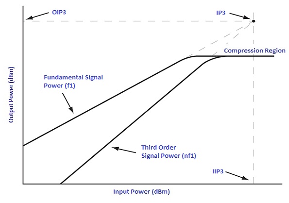
5 Third Order Intercept point: TOI is a point is a theoretical value in the linearity diagram. Third order components of the signals will be generated at every amplification process. Amplifier gain will start to decline once it reaches the saturation point. If the input power keeps increasing, the fundamental signal power and third order signal power will meet at a particular point. This point is known as third order intercept point. This calculation is used to determine the non-linearity behaviour of amplifiers during design.

Third order intercept point
6 Adjacent Channel Rejection Ratio: In practical scenario, a tiny percentage of the power transmitted through the desired channel will leak to the adjacent channels due to intermodulation distortion. ACLR is a ratio between the transmitted channel power and the power measured at the adjacent channels. It is very significant in modern wireless communication systems like LTE where signals are transmitted via multiple channels within the allocated bandwidth. In some cases, power amplifier must be capable to handle modulated signals as well.
7 Noise Figure: noise figure is a ratio between the input signal to noise ration and output signal to noise ration of a power amplifier. The lower the noise figure value the better the performance of amplifier, Noise figure will always be greater than one because the output signal to noise ratio will be higher than input SNR.
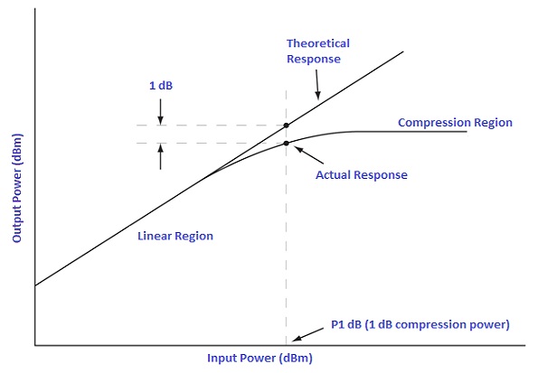
8 1 dB compression: Once amplifier reach a compression region, no amplification is possible and gain response will be flat. 1 dB compression point is a calculation point on the actual response curve of the linear diagram, one dB below the linear line where the amplifier starts to saturate its gain and become non linear.

1 dB compression point
9 Peak to Average Power Ratio: is a ratio between the peak signal power and average signal power level.
10 Maximum input and output power: maximum input and output power handling must be considered during selection of an RF power amplifier. Exceeding input power level could damage an amplifier and it is critical if you are cascading more than one amplifier units. Output power level must be sufficient to support the requirements after considering the flatness and losses across the operating bandwidth.
11 Size and power consumption: physical size must be considered while choosing an RF amplifier. Amplifiers are available from millimeter size to few meters wide and tall. It has to be selected according to the application and the environment. Most of the power amplifier generates heat during its operation. In order to have a proper functioning, a good air circulation has to be provided. Power consumption is another factor to keep in mind, some models requires high AC power supply and external cooling system especially those operating at very high power. There are models which require external power supply for its functioning.
Conclusion
Selection of an RF power amplifier is depends on many factors as stated above. Amplifier specifications can be found on data sheet from the manufacturer. S-parameters of the amplifier may be required for some evaluation and design. Well matched amplifiers are critical for efficiency in signal transmission and receiving systems. Most importantly it must suit your application and requirements in all aspects.

 English
  中文
中文